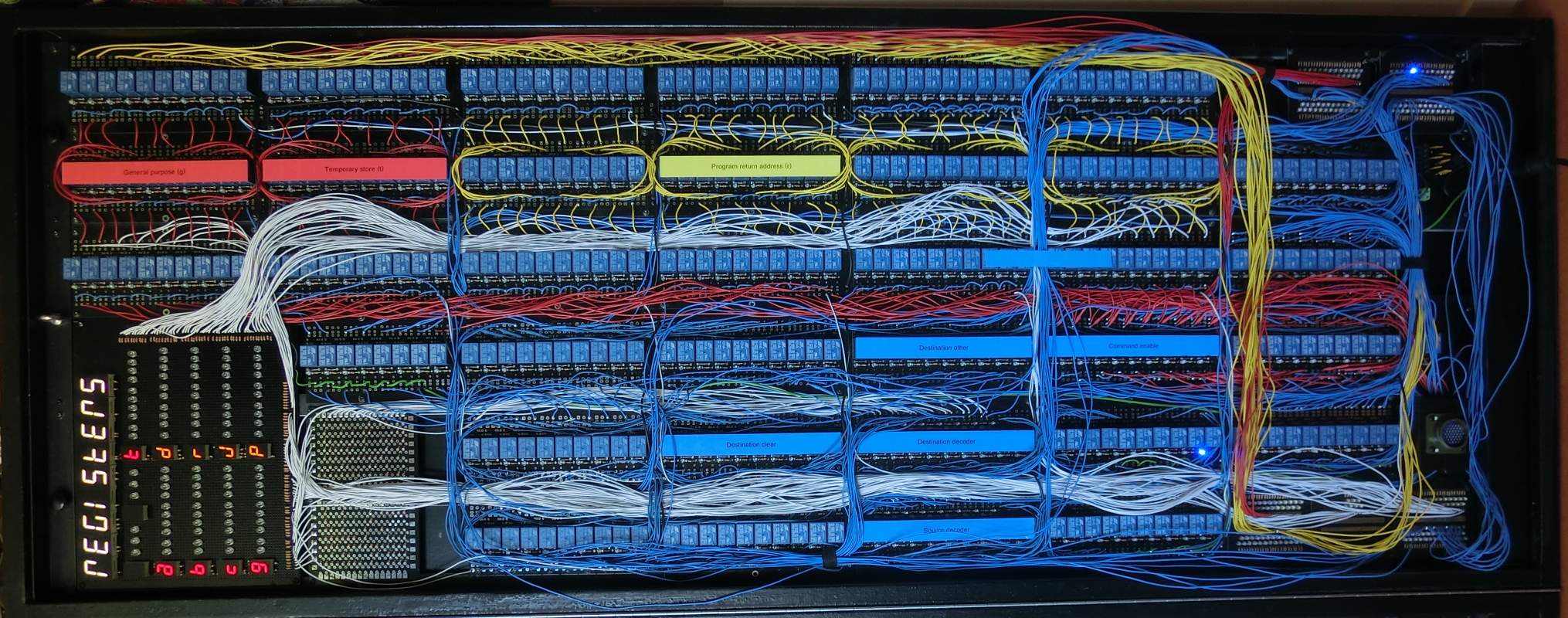
MERCIA has 12 registers in total. Since there are only three bits for register encoding are available in the instruction, seven (1-7) registers can be addressed by the user. Five more registers (8-12) can be addressed by the Microcode. The last three (13-15) are virtual registers. They are used to connect the results of the binary to 7-segment encoder to the databus.
|
|
Source |
|
|
Destination |
|
||||
|
Code |
Letter |
Register |
left |
Clear |
right |
left |
Clear |
right |
|
|
0 |
0000 |
- |
Not used |
- |
- |
- |
- |
- |
- |
|
1 |
0001 |
a |
Data a |
data |
clear |
address |
data |
clear |
address |
|
2 |
0010 |
b |
Data b |
data |
clear |
address |
data |
clear |
address |
|
3 |
0011 |
c |
Data c |
data |
clear |
address |
data |
clear |
address |
|
4 |
0100 |
g |
General purpose |
data |
clear |
address |
data |
clear |
address |
|
9 |
0101 |
t |
Temporary store |
data |
clear |
decoder |
data |
clear |
decoder |
|
5 |
0110 |
d |
Data pointer |
data |
clear |
address |
data |
clear |
address |
|
7 |
0111 |
r |
Return address |
data |
clear |
address |
data |
clear |
address |
|
8 |
1000 |
j |
Jump base |
data |
clear |
address |
data |
clear |
address |
|
6 |
1001 |
p |
Program pointer |
data |
clear |
address |
data |
clear |
address |
|
10 |
1010 |
i |
Instruction register |
data |
clear |
- |
data |
clear |
- |
|
11 |
1011 |
m |
Memory register |
data |
clear |
|
data |
clear |
- |
|
12 |
1100 |
s |
Status register |
- |
- |
- |
data |
clear |
- |
|
13 |
1101 |
1 |
Binair to 7-segment MSB |
- |
- |
- |
signed |
clear |
data |
|
14 |
1110 |
2 |
Binair to 7-segment |
- |
- |
- |
hex |
- |
data |
|
15 |
1111 |
3 |
Binair to 7-segment LSB |
- |
- |
- |
- |
- |
data |
Register usage
Data a, b and c
These registers are mainly used to facilitate the ALU. Unary operations are operations with one operand that uses a source and a destination register. Binary operations are operations with two operands that uses three registers: two for the input values and one for the result.
In the ALU command it is possible to define which of the three registers to use for input an which for output.
General purpose
This general purpose register can be freely used.
Temporary store
This register feeds the binary to 7-segment display encoder and is use by the Microcode to store intermediate results.
Data pointer
This register is used for array structures, where a pointer to the data is needed.
Program pointer
This register contains the value of the next program step to be executed.
Return address
If the execute command is performed, this register stores the return address. If multiple return addresses are needed this can be programmed, since this register can be accessed by the computer program.
Jump base
This register enables the relative addressing and stores the first byte (byte 0) of the program. If this register is zero, absolute addressing is used.
Instruction register
This register contains the current executed command.
Memory register
The memory register is used as a buffer for the memory.
Status register
The status register contains a number of status flags as discussed in the corresponding paragraph.
Register control
There are two issues that have to be addressed for register usage. First there is relay rumble, or the possibility that the output of a relay circuit will change a few times from 0 to 1 and vice versa, before all the relays have taken their final switching position. If this rumble produces a 1 before the final 0, the register will be set to 1, regardless the final value of the circuit. Secondly, a register can only be written when it is previously cleared en contains solely zeros.
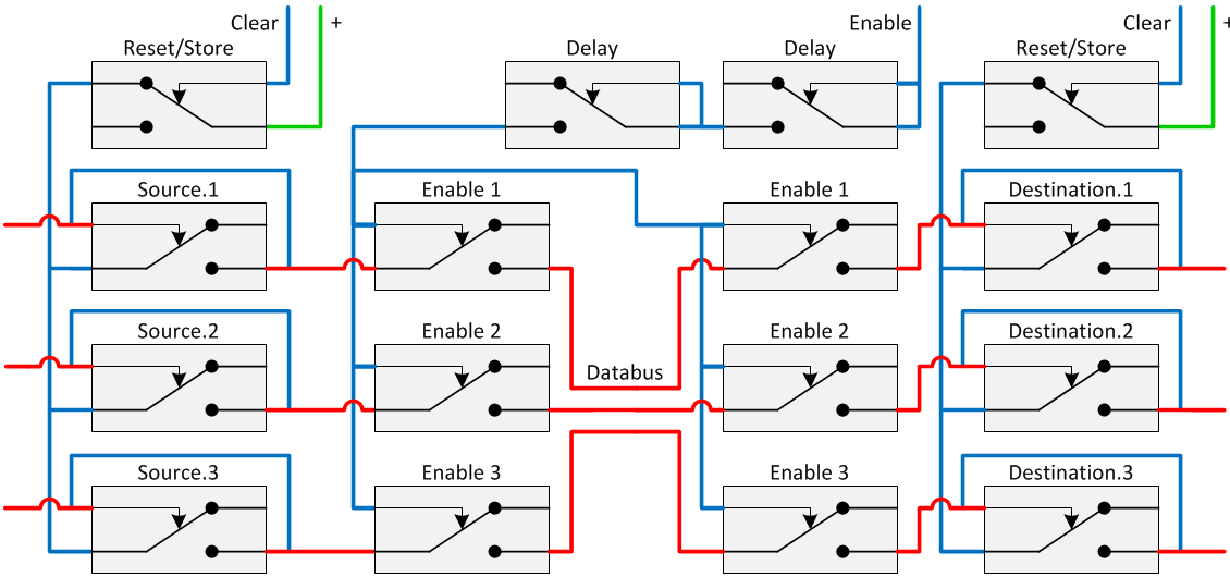
Both issues can be solved in a very elegant way as shown in the circuit diagram below. The solution lies in a delay in the enabling of the registers whilst clearing the destination register at the same time.

This enables the following sequence:
- The enable signal is set to 1. At the same time the clear signal of the destination register is set to 1.
- Then clear relay is activated and as a result of that the destination register is cleared.
- The register switch is set open, enabling the register.
- The feedback loop of the register is not enabled because the clear relay is still activated. Therefore the register will not hold the input value, effectively ignoring the register rumble.
- Both the enable signal and clear signals are set to 0.
- The clear relay is released and as a result of that, the register feedback loop is restored and the register will hold its value.
- The register switch is closed.
The registers are controlled by a four bit register decoder. The 15 outputs of this decoder are connected through an AND relay with the Enable left, Clear and Enable right lines. Because a copy operation involves two registers, there are two identical register controllers called Source and Destination. The outputs from the source and destination decoders for the same enable line, for instance enable left a, are connected through a diode OR port.

The instruction register
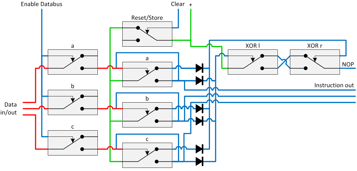
The instruction register holds the instruction that is executed. In order to handle memory problems, instructions containing all 0 or all 1 are treated as No Operation or NOP. The NOP needs to be detected in order to show this special situation as a NOP instruction. NOP detection is done by connecting diodes to the instruction register, as in principle shown in the following circuit diagram.

Two signals are generated: connected to the NC-contact, a signal is generated that is 0 when all bits are 1 and connected to the NO-contact, a signal is generated that is 0 when all bits are 0. Both signals are XOR-ed together and the NOP detection emerges. The same principle is used to determine weather the Jump base is not used (all bits are 0) or used (one or more bits are 1).
The status register
The status register is a special register that is used for conditional jumping. It is controlled in the same way as the other registers are. Three of the statusbits in the status register are connected to the databus, one to the ALU:
- If only one of the ten bits equals 1, the not equal to zero status is set to 1.
- For the multiplication of binary numbers, the odd condition has been created: if bit 0 is 1, the odd status is set to 1.
- For the multiplication of signed numbers (two's complement) with Booth's algorithm, the comparison of the databits d0 and d1 has been created. D0 XNOR d1 will set the bit to 1.
- If bit 9 is 1, the negative number status is set to 1.
- The status bit for the fourth status, the numeric overflow is derived directly from the ALU. When the carry of bit 9 is 1, this status bit is set to 1.

The condition decoder is used to generate the two conditions. Conditions are used for conditional jumping and for instruction variants. An instruction variant is an instruction that can be executed in more (maximal 4) way’s. There are two sets of conditions basic conditions and alternative conditions.
The basic conditions are 1. the instruction condition equals the status register and 2. the situation that bit0, bit 1 and bit2 are all zero. For the alternative conditions, bits 0 and 1 are used. This is shown in the next circuit diagram.

Januari 2019, Jeroen Brinkman


